Category Archives: Industries

Shrinking the Carbon Footprint in the Industrial Sector

1-bluemarble_west


To celebrate Earth Day, Design World published an article on how design engineers can help reduce the environmental impact of industry. In 2011,  the Energy Information Administration (EIA) found that the industrial sector was responsible for 51 percent of global energy consumption. Of the Industry’s energy use, 25 percent was in the form of losses. While this poses a major problem, author Danielle Collins offers several tips for how designers can reverse this environmental impact. Here are some of the things we learned:

Proper Sizing Helps Eliminate Inefficiency:

According to the article, “For linear motion components and systems, no other aspect of design has as much influence on energy use and efficiency as their physical size. Not only does proper sizing ensure the best performance for the application, avoiding waste in terms of scrap, rework, and over- or under-production. It also ensures that the driving equipment, whether electric, pneumatic or hydraulic, is not over-sized, which results in higher energy consumption.”

Collins uses linear bearings as an example to make her point. When larger bearings are used, larger motors, couplings and mounts also have to be used to create a proper inertia match,  While keeping safety factors in mind, Collins says that all the weight necessary to accommodate the large bearings leads to overall inefficiency.

Regular Maintenance Reduces Energy Consumption:

As equipment goes through cycle after cycle, eventually the lubrication will break down, which increases the friction and decreases efficiency. According to Collins, this leads to other parts such as the motor, gearboxes and cylinders to work harder and consume more energy.

Collins believes that although equipment maintenance isn’t so much the concern of the engineers, designing equipment that is  easy to maintain, such as that with ball chains or built-in lubrication systems, will more than likely keep machines running smoother and with less energy than those not built with low-maintenance considerations.

According to Collins, “Reducing the quantity and intervals for lubrication can also have a significant impact on the environmental footprint of a machine. A typical machine tool will have at least three linear axes of motion, with four bearings per axis, for a total of twelve bearings per machine. With approximately 250,000 machine tools produced each year, that’s over 3 million linear bearings to be lubricated! The potential for environmental impact due to lubricating greases and oils is considerable. Not to mention the energy required to move the axes.”

To read the full article and find out more on how designers can reduce energy consumption, click here.


Protecting Your Worm Gear Screw Jacks with Bellow Boots

On the production floor, worm gear jack products are constantly exposed to all kinds of harmful contaminates. With that in mind, it’s important to consider using solutions like bellow boots to protect your worm gear screw jack products. A boot protects the lifting shaft from contamination and helps retain lubricant to ensure long jack life.

bellows boots

Standard boots are sewn from black neoprene-covered nylon fabric for oil, water and weather resistance and are acceptable for use in -30° to +300°F environments. Optional materials are available for specific operating conditions. To understand which boots are best suited for your application, we’ve created a  template to make the process easier.

Standard boots are furnished with tie straps for jacks with greater than 65 inches travel. Tie straps are attached from convolution to convolution and help the boot extend uniformly.

Here is a chart of special boot materials and their respective temperature, range and application comments:

bellows boot chart

Integral Safety Threads

Ball nuts can fail for a variety of reasons. Primarily, it’s fatigue of the bearing balls or the threaded surface, which is why proper lubrication (link to lube blog post) is so important. However, ball nuts can fail prematurely due to misalignment, impact loading, contamination, or external damage to the return circuits. Premature failure may result in the loss of some or all of the balls between the nut and screw. When all the balls are lost the nut is no longer engaged with the screw and therefore may not move when the screw is rotated or, in vertical applications, will free fall along the screw.

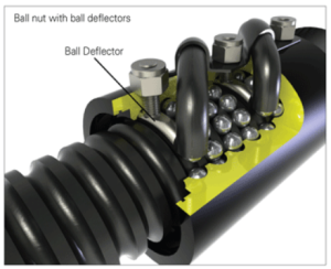
In applications where this loss of ball type failure could result in injury or death, this failure needs to be considered in the design. Possible preventative measures include the use of two or more screws supporting the load, use of nuts with multiple independent ball recirculation circuits, use of Ball Deflectors which prevent the balls from exiting the ball nut out the ends.

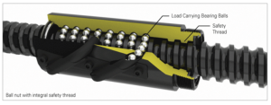
There is one more preventative measure that has proven itself in testing and in practical use; Integral Safety Threads. These unique solutions that provide the ball nut with a secondary safety thread – a reverse thread in the nut body itself. This special thread extends from the ID (Internal Diameter) of the nut to below the OD (Outside Diameter) of the screw without making contact. In the unlikely event that all the balls in the nut are lost, this “safety” thread will engage the screw and prevent free-fall. Although this thread can be used to lower the load to a safe position, it is not to be used otherwise. This can also be accomplished with the use of a special flange if the ball nut body cannot accommodate the Safety Thread feature.

integral 1 integral 2

CC Actuators 101

CC Actuators are a combination of an electric motor and an acme screw or a high efficiency ball screw. They are designed to be ready to install directly into any industrial or commercial application. They are ideally suited for any OEM application where linear motion is needed. These high-quality actuators feature:

  • Durable construction
  • Dependable performance
  • Long-life operation
  • High repeatability
  • Operation in either compression or tension loading applications
  • Adjustable limit switches
  • Lifetime lubrication
  • Mechanical overload protection
  • Corrosion resistant exterior surfaces

The most common applications are;

  • Telecommunications
  • Architectural Automation
  • Medical and Hospital Equipment
  • Semiconductor
  • Food Processing
  • Farm Equipment
  • Satellite Dish and Antenna Positioning

These rugged solutions come in standard travels of 4”, 12”, 18”, 24” or 36” with duty cycles typically around 30% max “on-time” of 5 minutes at rated load. Further versatility is provided by temperature ratings ranging from -30 to +160 F. Here’s a brief list of typical components, and what to look for when specifying;

Clutch – Should be heavy duty, in order to properly protect gears and components in the event of overload or overtravel.

Load Sensitive Brake – Should safely maintain the actuator’s position when at rest, without consuming power.

Boot – An optional accessory, but important in applications where you will want to protect the actuator tube from contaminants.

Limit Switch – Screw type limit switches offer precise positioning for travel up to 36”. Their design should allow for easily setting limits at both ends of travel. Optionally, Precision Limit Switches are typically available for shorter travel (under 24”) and will provide higher resolution adjustment.

Ball Screw – Look for precision ball screws made of high grade materials for greater efficiency & longer life

Sensors – There are a wide variety of sensor options for stroke control. Application needs should be the primary consideration when selecting, so look for a provider who offers a range.

Keyed – CC Linear Actuators may be ordered with a feature that allows the actuator tube to extend (retract) without being connected to the load. This key also reduces torque in clevises.

cc actuators

Advantages to Using Bevel Gear Jack Systems

Considering factors such as load, speed, torque and space, there’s no debate that bevel gear jack systems offer unique benefits to worm gear jack systems. The system’s long-duty cycle capabilities and multiple configurations make it a diverse product that suits a variety of applications.

Although worm gear jacks are sufficient for large loads that are infrequently moved, bevel gear jacks offer more flexibility and programmable options  for a wider range of applications.

Bevel gear jack systems don’t come with standardized travel lengths, so each one can be built to specification. Bevel screw jacks come available in machine and ball screw models. Machine screw jacks use a trapezoidal acme screw that offers a low backlash between the nut and screw. Ball screw jacks use hardened bearing balls that allow for smooth and efficient movement of the load. Bevel gear jacks have the capability to run continuously at 100-percent efficiency without overheating. Because of the greater efficiency and rolling action, the ball screw can operate at higher speeds or increased duty cycle when compared with the machine screw jack. 

Available in three jack configurations, bevel gear screws can move along the lift shaft in a variety of ways to meet customer expectations:

Translating- The translating configuration has a lifting shaft that moves through the gear box. A nut is integrated with the bevel gear such that the bevel gear and nut rotate together. When the lift shaft is held to prevent rotation, the lift shaft will move linearly through the gear box to move the load.

Rotating- A rotating jack has a lift shaft that moves a nut as it turns. The lift shaft is fixed to the bevel gear. This causes the load, which is
attached to the travel nut, to move along the lift shaft.

Keyed- The lift shaft of a translating style jack must be attached to something which prevents the lift shaft from rotating. If it is not, the lift shaft (and the load) will turn and not translate. A feature can be added to a machine screw jack to prevent lift shaft rotation. This type of jack is referred to as a “keyed jack” and is available in translating models.  Anti-rotation is accomplished by a square guide attached to the screw translating inside a square stem cover attached to the jack. The square stem tube is supplied with lube fittings.

Want to learn more about bevel gear screw jacks? Here’s a great video

bevel