Category Archives: Ball Screw Products

Worm Gear Essentials – Aesthetics

In the last of our series exploring the design considerations outlined in the white paper “How to Size a Worm Gear Screw Jack we look at the most esoteric of factors in determining the proper linear motion solution; the look of it.

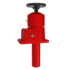
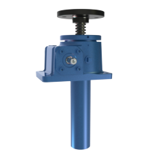
Sometimes the “human element” determines some of the design considerations of a jack. For instance, a small jack could lift a ton, but because of its small appearance, people could perceive the jack to be unsafe. Therefore, in applications where the jack is visible, larger jacks are often specified to bring a sense of comfort and scale. However, when jacks are buried within an application or machine, these types of human interaction considerations are not necessary.

Other look and feel considerations should also be taken into consideration. Will the jack need to be assessable for regular maintenance? Will it be in near a heavily trafficked area, susceptible to accidental damage or contact? Will it be overhead, and more prone to the need to “look” safe? These may seem like fuzzy questions to ask, but they are just as important to consider as any factor with a seemingly simple equation.

Useful tools:

Design Guide Pro app

Definitions and technical data

Arrangement templates

Multiple jack arrangements

Worm Gear Essentials – Duty Cycle

How does the ratio of run time to total cycle time affect the design and layout of a worm gear jack system? Taken from the white paper “How to Size a Worm Gear Screw Jack,” this post looks at what a designer has to take into account to properly and safely answer that question.

Some of the mechanical energy input to a worm gear screw jack is converted into heat caused by friction. The duty cycle is limited by the ability of the worm gear screw jack to dissipate heat. An increase in temperature can affect the properties of some components resulting in accelerated wear, damage and possible unexpected failure.

Recommended duty cycles at max horsepower are:

  • Ball screw jacks = 35% (65% time off)
  • Machine screw jacks = 25% (75% time off)

The choice between a ball screw jack and a machine screw jack can dictate size. Ball screw jacks are often chosen for their efficiency, allowing for an increased duty cycle and a smaller size jack to move a given load.

Useful tools:

Jack application data form

Design Guide Pro App

Worm gear screw jack design considerations

Worm Gear Essentials – Life

Here’s our 5th installment looking at the individual issues affecting Worm Gear system design originally highlighted in the white Paper “How to Size a Worm Gear Jack.” This posts looks at the expected life of a worm gear jack.

One of the benefits of using ball screw-style jacks is the ability to predict the theoretical life of the ball screw. The life of a ball nut used in a ball screw-style jacks can be easily calculated by using the following formula:

WHERE:

Tx  =  Travel other than rated load

Fr   =  Rated Dynamic Load for the ball nut

Fx  =  Actual or Equivalent load

Tr   = Rated Travel Life. For inch screws this is equal to 1,000,000 inches

For manufacturers wishing to extend the life of their screws, it can be beneficial to order a larger size jack than normally required, extending the life of the screw.

Since jack products often work in environments full of dirt and debris, manufacturers take multiple precautions to keep out contamination and preserve the life of the screw. Some manufacturers utilize bellows boots that expand and contract as the nut moves along to keep the lift shaft covered from contamination. Bellows boots can be supplied in numerous materials so that they may be applied in even the most extreme applications.

With ball screw jacks, another form of protection manufacturers use is wipers. Nut wipers can be felt or plastic, and brush the nut free of any dirt or other contaminants, keeping contaminants from entering the ball nut.

Related tools:

Bellows Boots Design

Boot Data Form

Design Guide Pro App

Worm Gear Essentials – Critical Speed

From the white paper “How to Size a Worm Gear Screw Jack” here’s a look at how critical speed helps determine the final design of a linear motion system.

Critical speed is the speed that excites the natural resonance frequency of the screw. The critical speed will vary with the diameter, unsupported length, end fixity and rpm of the screw. Since critical speed can also be affected by the shaft straightness and assembly alignment, it is recommended that the maximum speed be limited to 80 percent of the calculated critical speed. Due to the slow speeds at which jacks move, it is often not a large concern when choosing the size of a jack. However, critical speed should still be measured when making design considerations, especially when considering longer travel lift shafts.

Here is a simplified formula used for calculating critical speed for jacks:

WHERE:

N       =                Critical Speed (rpm)

d       =                Root Diameter of Screw (inch)

L        =                Length Between Bearing Supports (inch)

Cs      = End Fixity Factor

0.36 for mounting condition A

1.00 for mounting condition B

1.47 for mounting condition C

2.23 for mounting condition D


Related Tools:

Acme critical speed chart

Ball critical speed chart

Inch critical speed calculator

Metric critical speed calculator

Worm Gear Essentials – Column Strength

We’re looking at the elements that help a designer determine the right worm gear screw for an application, based off the excellent white paper “How to Size a Worm Gear Jack” from Ron Giovannone, Director of Application Engineering and Business Operations with Nook Industries in Cleveland, Ohio.

In this post, we look at how Column Strength factors into design considerations.

Column strength is the ability of the lift shaft to hold compressive loads without buckling. A compression load is a load that tends to squeeze the screw axially, which can cause buckling. With longer screw lengths, the column strength of the lift shaft may be substantially lower than nominal jack capacity.

In order to determine the compressibility of a given travel length, you must first determine your mounting condition.

A simplified formula to calculate the column strength in pounds is as follows:

WHERE:

Pcr          =             Maximum Load (lb)

d             =             Root Diameter of Screw (inch)

L              =             Distance between nut and load carrying bearing (inch)

Fc            =             End Fixity Factor

0.25 for mounting condition A

1.00 for mounting condition B

2.00 for mounting condition C

4.00 for mounting condition D

The above formula can only apply when the slenderness ratio (the length divided by the radius of gyration) is not exceeded.

Note: If you can ensure that the load will always be held in tension, you don’t need to consider column loading.

Related tools:

Inch Column Strength Calculator

Metric Column Strength Calculator