Tag Archives: linear motion design challenges

Worm Gear Essentials – Horsepower

The following is taken from an excellent white paper from Ron Givannone, Director of Application Engineering and Business Operations at Nook Industries (hyperlink). Titled “How to Size a Worm Gear Jack,” it looks at the key factors in figuring out what size and configuration of jack will work based on the needs of your application. Over the next few weeks, we’ll look at the different factors, and offer a bit more background.

This week, how Horsepower limitations can affect jack sizing.

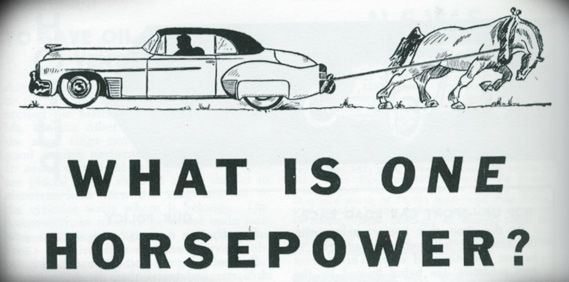
When determining the lifting power of a jack, it’s a common mistake to assume the lifting capabilities of a jack are determined solely by its tonnage size. The load’s capacity is more often determined by its horsepower limitations. For example, a 10-ton jack may only be able to lift a one-ton load, because it is temperature-limited by the working horsepower it requires to lift the load.

The horsepower limit of the jack is a result of its ability to dissipate the heat generated from the inefficiencies of its components. The maximum horsepower value represents the point at which the heat that is generated by the working horsepower to move a given load meets the maximum temperature of the internal components. The working horsepower to move a given load is calculated by using the following formula:

How well a jack can dissipate heat is influenced by many application-specific variables, including mounting, environment, duty cycle and lubrication. The best way to determine whether performance is within horsepower limits is to measure the jack temperature. The temperature of the housing near the worm gear must not exceed 200 degrees Fahrenheit.

Looking for help in figuring out the right horsepower? Here are some tools:

Calculate Horsepower with this calculator

Calculate Kilowatts

Worm gear jacks definitions and technical data

Wear Indicator Nuts for Worm Screw Jacks.

Nook Industries and Design World discuss how Wear Indicator Nuts for jacks can support your application.  Make Motion Work for you.

#MakingMotionWork with additional Nook Industries videos.

Standard Nook Logo

Nook Industries

Check out Nook Industries on The World’s Greatest!

#MakingMotionWork

Standard Nook Logo

Industry Insights at Arm’s Reach

With so many markets, products and changes happening  within the industry, it can be a challenge for designers to know where to find reliable and helpful information . Luckily, we’ve provided two companies who work hard in delivering topnotch, insightful content to help broaden your knowledge of the industry.

You might know Rockwell Automation as the world’s largest company for industrial automation and information, but did you know the company delivers a wide array of white papers, tools and other industrial automation methods, trends and technologies? The Journal from Rockwell  and Our PartnerNetwork™ recently published “The Basics of Ball Screws,” which teaches the key terms, preloading methods and calculations for understanding ball screws.

Rockwell also provides beneficial tools, such as its “Motion Analyzer,” which offers an inertia calculator and compatibility browser for a variety of different products, including linear motion products & systems.

Design World provides daily news in the industry, videos, tech tutorials, webinars and trending topics.According to its website, “Design World is written for engineers by engineers with an emphasis on applying the engineering fundamentals to real world machine design applications across industries including medical, packaging, semiconductor, material handling, and off-highway.” From pneumatics to robotics, the magazine and its digital brand stand as invaluable resources for designers and engineers who wish to be ahead of the curve in the latest industry happenings.


Getting the Best out of Your Linear Round Rail Bearings (Part 1)

In order to get the most life and best applications out of your bearings, it’s important to understand the size of the load, how the load will be applied and the length of the stroke. Applying too much weight to a load can significantly reduce the life and efficiency of your bearings. Also, incorrectly distributing the weight on the load can be harmful. In addition to some helpful design considerations, let’s take a look at the load considerations below.

Load ratings are the required design life, shaft hardness and bearing dynamic that affect the load and can be applied to a linear bearing. Two dynamic load ratings are given for each bearing size based on the rotational orientation of the bearing.

The normal load rating is used in applications where the orientation of the ball tracks relative to the load cannot be controlled. The normal load rating is based on a load imposed directly over a single ball track. The normal load rating shown in the specification tables is slightly greater than would be mathematically calculated based on one track loading, because it assumes that the load is shared to some degree by one or more of the adjacent ball tracks.

The maximum load rating assumes that the load is applied midway between two ball tracks as illustrated below. In this orientation the load is distributed over the maximum number of bearing balls.

The normal and maximum load ratings are based on a Rc 60 shaft hardness and a travel life of two million inches. For linear bearing system operating at less than full rated load, the Load-Life Curve may be used to determine the travel life expectancy.

An equivalent load value can be calculated when sizing linear bearings for applications at conditions other than maximum rating.

linear bearings