Electric Cylinders are commonly used in satellite dishes, solar panels and other large industrial environments. When dealing with Electric Cylinders, these 14 terms are essential to know:
1. BACKLASH
Backlash can sometimes be beneficial. While backlash can create inaccuracies, components that can tolerate a small amount of backlash can create space for contaminants to pass through the component. Backlash in cylinders occurs wherever reversible load conditions exist. Backlash is less than .015 inches for all but the largest cylinder models. Ball Screw Cylinders can be factory adjusted to reduce backlash at the lift shaft by selecting bearing ball size in the ball nut. This selective fit technique can be used to achieve a minimal lash between the ball nut and ball screw of .003 inches to .005 inches. Precision ball screws with preloaded nuts can be supplied when less than .003 inches of backlash is required.
 2. REACTION TORQUE
When an electric cylinder is used to move a load, the actuator tube must be secured to prevent rotation. The reaction torque required to prevent rotation is a function of the screw lead and the load applied on the cylinder. Prior to installation, the actuator tube can rotate freely in or out of the cylinder without movement of the input worm. This ability to rotate aids installation but prevents the optional rotary limit switch from being factory preset for end of travel positions. Rod-Type Limit Switches prevent tubes from freely rotating but are not intended to absorb the rod reaction torque.
3. TRAVEL LENGTH
Electric Cylinders are not pre-assembled or stocked with standard length screws. Each cylinder is made to order based on travel length. Cylinders can be built with non-standard lead screws to change the cylinder’s operating speed, or if required, ground or preloaded screws.
4. LEAD ACCURACY
Lead accuracy is the difference between the actual distance traveled and the theoretical distance traveled based on lead. For example: Consider a lift shaft with a .5-inch lead and ± .004-inch/ foot lead accuracy. If the shaft is rotated 24 times, the distance the nut moves is 11.996 to 12.004 inches. The rolled thread screws, as employed in products, are held within ± .004-inch-per-foot lead error.
5. INPUT TORQUE
The input torque is the rotary force required at the input of the cylinder to generate an output force at the actuator tube. This number, multiplied by the load, is the required input torque.
6. INPUT SPEED
DD and RAD Electric Cylinder models are rated at 1,725 rpm input. If provided with a servo motor, cylinders may be operated up to 3,000 rpm provided horsepower and temperature ratings are not exceeded.
NOTE: Maximum horsepower values should not be exceeded.
7. DUTY CYCLE
Duty cycle is the ratio of run time to total cycle time. Some of the electrical energy input to an electric cylinder is converted into heat. The duty cycle is limited by the ability of the electric cylinder to dissipate this heat. An increase in temperature can affect the properties of some components resulting in accelerated wear, damage and possible unexpected failure.
 8. SELF-LOCKING AND BREAKS
Self-locking occurs when system efficiencies are low enough that the force on the actuator lifting tube cannot cause the drive system to reverse direction. Electric Cylinders that utilize acme screws and have ratios of 20-to-1 or greater are self-locking and, in the absence of vibration, hold loads without backdriving. All other models require a motor brake to prevent backdriving.
10. END-OF-TRAVEL STOPS
Travel stops are not standard. A limit switch and a brake should be used to stop the motor. Mechanical stops can cause damage to the cylinders because most electric motors will deliver stall torques much higher than their rated torques and motor inertia can cause severe shock loads. For hand operation, mechanical stops can be provided.
11. MAXIMUM LOAD
The maximum load is the thrust load, including shock, that can be applied to the actuator without damaging the assembly.
12. DYNAMIC CAPACITY
The dynamic capacity is the maximum allowable thrust load based on horsepower, thrust bearing and screw limitation. The dynamic capacity can determine the life of a given material.
13. TENSION LOAD
A tension load is the load that tends to stretch the screw. Good materials should be able to retain stiffness and withstand stretching.
14. COMPRESSION LOAD
A compression load is the load that tends to squeeze the screw. Good materials should be able to withstand buckling and maintain straight columns.

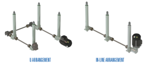
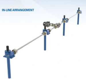 To give you an idea of how an in-line arrangement works in a company’s favor, here’s a real-life scenario to observe: A steel tube manufacturer is developing a new OD polisher that will increase production by 22 percent. Because of the increased production time, the set-up crew is unable to set the feed table manually and is looking to automate the feed table height using screw jack actuators.
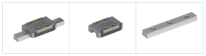
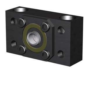 Some customers have made their own ball screw supports, usually paired on either side of the ball nut in pairs of 2, 4 or 6, to reduce the unsupported distance, essentially quadrupling the critical speed for each pair used. Depending on the application, they can even allow you to select a smaller diameter ball screw, without compromising performance.