8 Factors You Need to Consider
No matter the type of worm gear jack, machine or ball, there are 8 factors that need to be known and addressed in the design of a solution. In this post, we’ll start looking at these design constraints and how they can determine the sizing, placement and configuration of your worm gear jack screw.
 1. Load Capacity
The load capacity of the jack is limited by the physical constraints of the components (drive sleeve, lift shaft, bearings, etc.). All types of anticipated loads must be calculated, and be within the rated capacity of the jack. These loads can include: static, dynamic, moving, acceleration/deceleration loads as well as cutting and other reaction forces.
Appropriate design should also be made for shock loads, and should not exceed the rated capacity of the jack.
To accommodate accidental overloads, jacks can sustain the following overload conditions without damage – 10% for dynamic loads, 30% for static.
2. Duty Cycle
Duty cycle is the percentage of time on as opposed to total time. Recommended duty cycles for the two styles of jacks at max horsepower are:
• Ball screw jacks 35% (65% off)
• Machine screw jacks 25% (75% off)
The largest determining factor in calculating duty cycle is the ability of the jack to dissipate heat that builds up during operation. Anything that reduces or increases the generated heat increases or decreases duty cycle accordingly. Additionally, jacks may be limited by their maximum operating temperature (200°F) and not duty cycle.
 3. Horsepower Ratings
Horsepower values are influenced by many application-specific variables including mounting, environment, duty cycle and lubrication. The best way to determine whether performance is within horsepower limits is to measure the jack temperature. The temperature of the housing near the worm must not exceed 200°F.
The horsepower limit of a jack is a result of the ability to dissipate the heat generated from the inefficiencies of its components, based on intermittent operation. Special consideration should be given for multiple jack arrangements, as total horsepower required depends on horsepower per jack, number of jacks, the efficiency of the gear box or boxes and the efficiency of the arrangement.
If needed horsepower exceeds the maximum for the jack selected, several solutions are possible:
• Use a larger jack
• If it is a Machine Screw Jack, look at a comparable Ball Screw Jack
• Operate at a lower input speed
• Use a right angle reducer
 4. Column Strength
Column Strength is the ability of the lift shaft to hold compressive loads without buckling. With longer screw lengths, column strength can be substantially lower than nominal jack capacity.
If the lift shaft is in tension only, the screw jack travel is limited by the available screw material or by the critical speed of the screw. If there is any possibility for the lift shaft to go into compression, the application should be sized for sufficient column strength. Designers should also be aware of effects of side loading. Jacks operating horizontally with long lift shafts can experience bending from the weight of the screw.
If column strength is exceeded, there are several options:
• Change the jack configuration in order to put the shaft in tension
• Increase jack size
• Add a bearing mount for rotating jacks
• Change the lift shaft mounting condition, for example, from clevis to top plate
5. Critical Speed
The speed that excites the natural frequency of the screw is referred to as the critical speed. The critical speed will vary with the diameter, unsupported length, end fixity and rpm of the screw.
Because of the nature of most screw jack applications, critical speed is often overlooked. However, with longer travels, critical speed should be a major factor in determining the appropriate size jack. Since critical speed can also be affected by the shaft straightness and assembly alignment, it is recommended that the maximum speed be limited to 80% of the calculated critical speed.
 6. Type of Guidance
All linear motion systems require both thrust & guidance. Worm gear jacks are designed to provide thrust only and a guidance system should be designed to absorb all loads other than thrust. Preferred systems include hardened ground round shafting or square profile rail.
7. Brakemotor Sizing
To ensure safety, a brakemotor is recommended for worm gear jack screws where there is the possibility of injury. Horsepower requirements will determine the size of the motor, and once selected, verify that the standard brake has sufficient torque to both stop and hold the load.
Lastly, high lead ball screws may require larger, nonstandard brakes to stop the load, to ensure against excessive “drift” when stopping.
8. Ball Screw Life
A major benefit of the use of ball screw jacks is the ability to predict the theoretical life of the ball screw, and all major manufacturers will provide life charts for their products.
Once these factors are understood and accounted for, and paired with the features and benefits of Machine and Ball Screw Jacks, selecting the right one for your application should be considerably easier.


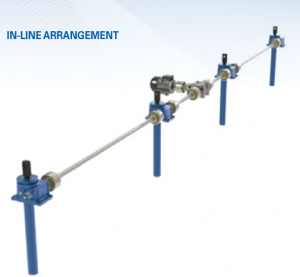 To give you an idea of how an in-line arrangement works in a company’s favor, here’s a real-life scenario to observe: A steel tube manufacturer is developing a new OD polisher that will increase production by 22 percent. Because of the increased production time, the set-up crew is unable to set the feed table manually and is looking to automate the feed table height using screw jack actuators.