3D Printers – Leading the 3rd Industrial Revolution

Late last year, Design World editor, Danielle Collins, posted a great article about the “3rd Industrial Revolution.”

News flash—we’re in it, and 3D printers are leading the way.

Costs are coming down almost as fast as accuracy is increasing. From the industrial creation of finished parts, to the maker movement-led DIY creation of home models, 3D printers are increasingly becoming a more viable technology across different industries and applications.

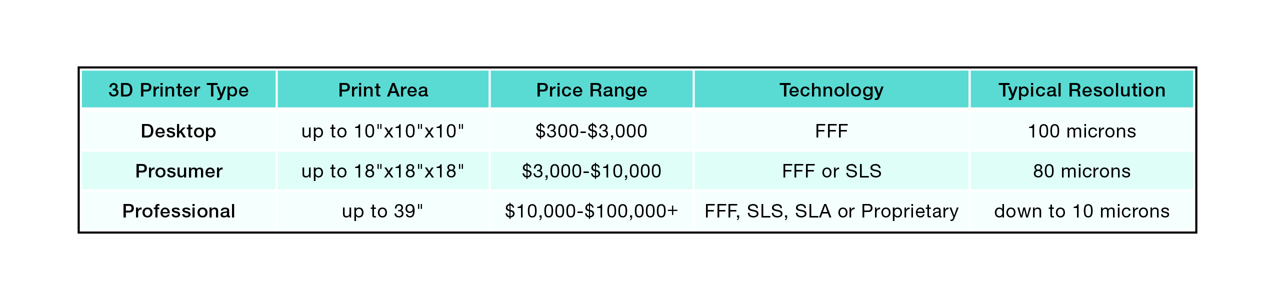
Collins sorts printers into 3 basic categories, each with unique offerings and challenges:

  • Desktop
    • Generally 10x10x10 or smaller.
    • Low cost kits to fully assembled models.
    • Utilize FreeForm Fabrication, or FFF for printing.
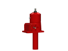
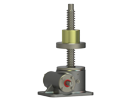
    • Relatively low-tech linear motion solutions; typically round shafts or belt-pulley systems.
    • Prone to alignment issues, such as binding and torque spikes, as well as backlash.
  • Prosumer
    • Print areas around 18x18x18.
    • FFF or Selective Laser Sintering (SLS) methods of printing.
    • SLS offers more material choices including metal, ceramic and plastic.
    • Ideal for part modeling or rapid prototyping.
    • Rely mainly on linear rails and lead screws.
  • Professional/Industrial Grade
    • Print areas of up to a cubic meter.
    • FFF, SLS, Stereolithography (SLA) or in some cases unique, proprietary, deposition methods.
    • Highest resolution (layer thickness) as well as better surface finish and faster build times.
    • High-precision parts, functional prototypes, finished parts and printed electronics.
    • Utilized the most advanced linear motion solutions. But Collins notes that even these might not be accurate enough for some projects, and custom solutions will become necessary.

This handy chart, also from the article, helps lay out the features of all 3 types (click for a clearer view).

NOO-040_Chart

So, what has your experience with 3D printing been? Are you using them at all, investigating the options or already incorporating them as a part of your business?

When to use Ball Screw Jacks vs. Machine Screw Jacks

 inch ball Stainless machine upright

Tips for how to select the right one for your application
Worm Gear Screws Jacks can provide long duty life, high load capacity and flexible design. They come in two major categories, Ball Screw and Machine Screw. In this post, we hope to help you identify the best type for your application.

Ball Screw Jacks use a ball screw and nut made from hardened alloy steel with bearing balls carrying the load between nut & screw. This rolling action reduces the friction between nut and screw, permitting smooth and efficient load movement that requires approximately 1/3 less torque than a machine screw jack with the same load.

Machine Screw Jacks incorporate an alloy or sometimes stainless steel worm which drives a high strength bronze worm gear, or drive sleeve. The worm shaft is supported on anti-friction tapered roller bearings with external seals that prevent lubrication loss. The drive sleeve can also be supported on tapered roller bearings, or ball thrust bearings. Rotation of the drive sleeve causes the acme thread lifting screw to translate or rotate, depending on the jack configuration.

Because of their efficiency and lower power requirements, Ball Screw Jacks are often preferred. However, several factors can make Machine Screw Jacks preferable. For quick reference …

Machine Screw Jacks are best used for:
• Resistance to backdriving
• Environments with vibration
• Manual operation
• High static loads
• Corrosion resistance (with stainless steel versions)

Ball Screw Jacks are preferred for:
• Long travel lengths
• Long, predictable life
• High duty cycles
• Oscillating motion

Both types can be metric or inch, come in several types (Upright, Inverted, Upright Rotating and Inverted Rotating) and multiple jacks can be laid out in H, U, T and In-Line arrangement.

You can also employ multiple jacks in tandem, depending on the physical design and size of the equipment, its stiffness and the guide system. This will, however, introduce challenges with drive, alignment and synchronization.

Any jack system is limited by multiple constraints: load capacity, duty cycle, horsepower, column strength, critical speed, type of guidance, brakemotor size and ball screw life. To properly size your jack for these constraints, application information must be collected.

A Nook Industries Publication