Tag Archives: linear motion

All Your Equations In One Place

calculators

When a linear motion solution is in place & running, it’s easy for the casual observer to think it looks easy. That’s what our industry is all about; making the difficult or even impossible look easy.

But what few people outside the industry realize is just how much work needs to go into the design of a successful linear motion system. The old adage “Measure twice, cut once” doesn’t even begin to cover all the variables, that have to be dealt with.

Now, a new app looks to make that successful design at least a little easier. The Design Guide Pro not only offers selectors for Bevel Gears, Worm Gear Jacks, Bearings and Electric Cylinders, but it also has a calculator section. Here, you’ll find tools to help you establish Energy, Critical Speed, Column Load, Torque and Nut Life as well as helping with Unit Conversions.

All in the palm of your hand. Check it out today by clicking here.

#MakingMotionWork

Integral Safety Threads

Ball nuts can fail for a variety of reasons. Primarily, it’s fatigue of the bearing balls or the threaded surface, which is why proper lubrication (link to lube blog post) is so important. However, ball nuts can fail prematurely due to misalignment, impact loading, contamination, or external damage to the return circuits. Premature failure may result in the loss of some or all of the balls between the nut and screw. When all the balls are lost the nut is no longer engaged with the screw and therefore may not move when the screw is rotated or, in vertical applications, will free fall along the screw.

In applications where this loss of ball type failure could result in injury or death, this failure needs to be considered in the design. Possible preventative measures include the use of two or more screws supporting the load, use of nuts with multiple independent ball recirculation circuits, use of Ball Deflectors which prevent the balls from exiting the ball nut out the ends.

There is one more preventative measure that has proven itself in testing and in practical use; Integral Safety Threads. These unique solutions that provide the ball nut with a secondary safety thread – a reverse thread in the nut body itself. This special thread extends from the ID (Internal Diameter) of the nut to below the OD (Outside Diameter) of the screw without making contact. In the unlikely event that all the balls in the nut are lost, this “safety” thread will engage the screw and prevent free-fall. Although this thread can be used to lower the load to a safe position, it is not to be used otherwise. This can also be accomplished with the use of a special flange if the ball nut body cannot accommodate the Safety Thread feature.

integral 1 integral 2

CC Actuators 101

CC Actuators are a combination of an electric motor and an acme screw or a high efficiency ball screw. They are designed to be ready to install directly into any industrial or commercial application. They are ideally suited for any OEM application where linear motion is needed. These high-quality actuators feature:

  • Durable construction
  • Dependable performance
  • Long-life operation
  • High repeatability
  • Operation in either compression or tension loading applications
  • Adjustable limit switches
  • Lifetime lubrication
  • Mechanical overload protection
  • Corrosion resistant exterior surfaces

The most common applications are;

  • Telecommunications
  • Architectural Automation
  • Medical and Hospital Equipment
  • Semiconductor
  • Food Processing
  • Farm Equipment
  • Satellite Dish and Antenna Positioning

These rugged solutions come in standard travels of 4”, 12”, 18”, 24” or 36” with duty cycles typically around 30% max “on-time” of 5 minutes at rated load. Further versatility is provided by temperature ratings ranging from -30 to +160 F. Here’s a brief list of typical components, and what to look for when specifying;

Clutch – Should be heavy duty, in order to properly protect gears and components in the event of overload or overtravel.

Load Sensitive Brake – Should safely maintain the actuator’s position when at rest, without consuming power.

Boot – An optional accessory, but important in applications where you will want to protect the actuator tube from contaminants.

Limit Switch – Screw type limit switches offer precise positioning for travel up to 36”. Their design should allow for easily setting limits at both ends of travel. Optionally, Precision Limit Switches are typically available for shorter travel (under 24”) and will provide higher resolution adjustment.

Ball Screw – Look for precision ball screws made of high grade materials for greater efficiency & longer life

Sensors – There are a wide variety of sensor options for stroke control. Application needs should be the primary consideration when selecting, so look for a provider who offers a range.

Keyed – CC Linear Actuators may be ordered with a feature that allows the actuator tube to extend (retract) without being connected to the load. This key also reduces torque in clevises.

cc actuators

When to use Ball Screw Jacks vs. Machine Screw Jacks

 inch ball Stainless machine upright

Tips for how to select the right one for your application
Worm Gear Screws Jacks can provide long duty life, high load capacity and flexible design. They come in two major categories, Ball Screw and Machine Screw. In this post, we hope to help you identify the best type for your application.

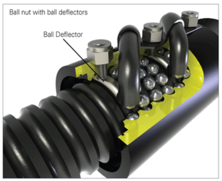
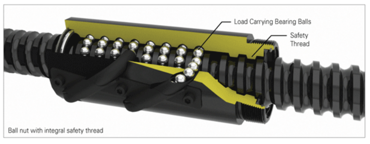
Ball Screw Jacks use a ball screw and nut made from hardened alloy steel with bearing balls carrying the load between nut & screw. This rolling action reduces the friction between nut and screw, permitting smooth and efficient load movement that requires approximately 1/3 less torque than a machine screw jack with the same load.

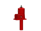
Machine Screw Jacks incorporate an alloy or sometimes stainless steel worm which drives a high strength bronze worm gear, or drive sleeve. The worm shaft is supported on anti-friction tapered roller bearings with external seals that prevent lubrication loss. The drive sleeve can also be supported on tapered roller bearings, or ball thrust bearings. Rotation of the drive sleeve causes the acme thread lifting screw to translate or rotate, depending on the jack configuration.

Because of their efficiency and lower power requirements, Ball Screw Jacks are often preferred. However, several factors can make Machine Screw Jacks preferable. For quick reference …

Machine Screw Jacks are best used for:
• Resistance to backdriving
• Environments with vibration
• Manual operation
• High static loads
• Corrosion resistance (with stainless steel versions)

Ball Screw Jacks are preferred for:
• Long travel lengths
• Long, predictable life
• High duty cycles
• Oscillating motion

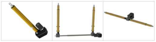
Both types can be metric or inch, come in several types (Upright, Inverted, Upright Rotating and Inverted Rotating) and multiple jacks can be laid out in H, U, T and In-Line arrangement.

You can also employ multiple jacks in tandem, depending on the physical design and size of the equipment, its stiffness and the guide system. This will, however, introduce challenges with drive, alignment and synchronization.

Any jack system is limited by multiple constraints: load capacity, duty cycle, horsepower, column strength, critical speed, type of guidance, brakemotor size and ball screw life. To properly size your jack for these constraints, application information must be collected.