When considering the vast majority of applications in which machine screws are used, it’s important to review the functions of some of the major types of screws. Below, we’ll take a look at the designs, functions and more while we define acme, ball and planetary screws.
Acme Screws:
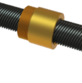
The acme screw thread, sometimes referred to as the trapezoidal thread, is used for lead screws. They are often needed for large loads, or when the environment is less than desirable.
The acme thread form has been around for over a century, replacing square thread screws which had straight-sided flanks and were difficult to manufacture.
There are two main classes of acme thread forms: general purpose (G) and centralizing (C). The general purpose and centralizing thread forms have a nominal depth of thread of 0.50 x pitch and have a 29 degree included thread angle, which has allowed companies to develop unique screw diameters and leads. European metric Trapezoidal thread forms have a 30 degree Included thread angle.
When compared to general-purpose thread forms, centralizing threads are manufactured with tighter tolerances and reduced clearance on the major diameter. For instance; If an acme nut is side loaded with a radial load, a “G” class will wedge when the nut thread flanks come in contact with the screw thread flanks. To prevent this wedging, a “C” class thread form can be used, since it utilizes less clearance and tighter tolerances are allowed between the major diameter of the nut and the major diameter of the screw.
Industry leaders have developed several unique thread forms, such as stub acme forms and 40 degree included angle, which allow them to provide a variety of diameter and lead combinations.
Ball Screws:
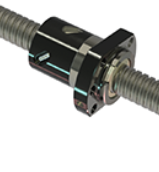
For loads requiring a greater amount of efficiency, companies often turn to ball screws. A ball screw assembly is a device comprised of a nut, screw, and reciprocating ball bearings. The bearings provide the thread engagement between the nut and screw.
Ball screws offer an efficient means for converting rotary motion to linear motion. A ball screw is an improvement over an acme screw just as an anti-friction ball bearing is an improvement over a plain bushing.
In the long run, ball screw systems can prove to be a cost-effective alternative to pneumatic or hydraulic systems, which require constant electrical and air power.
Planetary Roller Screws:
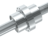
Planetary roller screws are remarkable devices designed to convert rotary motion into axial force or vice versa.
The planetary roller screw design offers multiple advantages and reliability for the most demanding applications when compared with other lead screw types due to its rolling motion. These screws offer high efficiency even in relatively shallow lead designs.
The multitude of contact points can carry large loads and provide very high resolution (small axial movement) when using very shallow leads. Planetary roller screws produce high rotational speeds with faster acceleration without adverse effects.

 For example, a leading cookie manufacturer could be adding a new product that requires a greater distance to the top heating element of the conveyor oven. The oven originally only had a static-top heating element and with this new order, it needs to be adjustable up to 14 inches. The top heating element weighs 5,000 pounds. The manufacturer anticipates only making adjustments to the height once or twice a month.
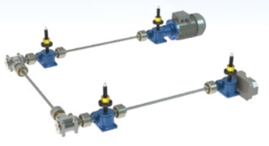
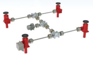 An example of this arrangement could be a manufacturer of steel frames for the commercial dairy industry is building a material lift which contains a stack of prefabricated frames. The material lift will index up as each frame is removed by an automated grip from the top of the stack. The jack will index up 1 inch in 2 seconds every 30 seconds. After the last frame is removed, the jacks will fully retract to the collapsed position in 6 seconds waiting for the next load of frames. Complete cycle time is 10 minutes running 6 hours per day, 5 days a week. The design calls for a four-jack arrangement lifting from underneath the lifting stage, driven by a single motor.