Category Archives: Products

Helpful Terms and Tips for Understanding Precision Ball Splines

Ball Splines are convenient and efficient devices that allow friction-free linear motion while transmitting torque. Because of their reliability and high efficiency, they are utilized to replace conventional splines. In a ball spline assembly, recirculating bearing balls carry the load between the rotating member (inner race) and the rotating/translating member (outer race). These defined terms, processes and applications will give you a better idea of how and why ball splines matter in the precision engineering industry.

10 BALL SPLINE TERMS:

1. ACTIVE CIRCUITS

The closed path that the bearing balls follow through the outer race is referred to as a circuit. The number of potential circuits varies with the diameter of the spline shaft. When a circuit is loaded with bearing balls, it is referred to as an “active circuit.”

2. RETURN GUIDES

The outer race component through which the bearing balls are recirculated is referred to as the return guide.

3. BALL CIRCLE DIAMETER

The ball circle diameter is the diameter of the circle generated by the center of the bearing balls when in contact with the inner and outer race.

4. LAND DIAMETER

The land diameter is the outside diameter of the inner race. This diameter is less than the ball circle diameter.

5. ROOT DIAMETER

The root diameter is the diameter of the inner race measured at the bottom of the groove. This is the diameter used for critical speed calculations.

6. STRAIGHTNESS

Internal stresses may cause the material to bend. When ordering random lengths or cut material without end machining, straightening is recommended. Handling or machining of splines can also cause the material to bend. Before, during and after machining, additional straightening may be required.

7. LIFE

A ball spline assembly uses rolling elements to carry a load similar to an anti-friction (ball) bearing. These elements do not wear when properly lubricated during normal use. Therefore, ball spline life is predictable and is determined by calculating the fatigue failure of the components.

8. FRICTION

The use of rolling elements in a ball spline results in a low coefficient of friction.

9. ROTATIONAL LASH

Backlash or lash is the relative rotational movement of an outer race with no rotation of the inner race (or vice versa).

10. SELECTIVE FIT

When less than standard lash is required and a pre-loaded outer race cannot be used, outer races can be custom fit to a specific inner race with bearing balls selected to minimize rotational (angular) lash.


FIVE  LOAD DEFINITIONS:

1. DYNAMIC TORQUE LOAD

The dynamic torque load is the torque load which, when applied to the ball spline assembly, will allow a minimum life of 1,000,000 inches of travel.

2. STATIC TORQUE LOAD

This is the maximum torque load (including shock) that can be applied to the spline assembly without damaging the assembly.

3. OVERTURNING LOAD

A load that rotates the outer race around the longitudinal axis of the inner race is an overturning load.

4. SIDE LOAD

This is a load that is applied radially to the outer race.  Although a side load will not prevent the ball spline from operating, the outer race is not designed to operate with a side load, such as those generated from pulleys, drive belts or misalignment.

5. PRELOAD

Preload is a load introduced between an outer race and screw assembly that eliminates radial movement. Preloaded assemblies provide zero backlash for excellent repeatability and increased system stiffness.


OPTIONAL STANDARD KEYWAYS

Typically, outer races are mounted by machining a keyway into the outer race, inserting a key, and then sliding the outer race into a keyed bore. Standard machined keyways are available.


TRANSFERRING OUTER RACES FROM SHIPPING ARBOR:

STANDARD RACES

Ball spline outer races are shipped on arbors. Transferring the outer race from the arbor to the ball spline can be achieved by placing the arbor against the end of the spline and carefully sliding the outer race onto the inner race.

If the I.D. of the arbor is not able to slip over the O.D. of the end journal, apply tape to the journal to bring the O.D. up to the root diameter. The outer race can then be transferred across the taped journal onto the ball spline. Removal of the arbor from the outer race will result in the loss of the bearing balls. The set screw is used for transportation only and needs to be completely removed after installation.


LUBRICATION

Proper and frequent lubrication must be provided to achieve predicted service life. A 90% reduction in the ball spline life should be anticipated when operating without lubricants.

Standard lubrication practices for antifriction bearings should be followed when lubricating ball splines. A light oil or grease (lithium-based) is suitable for most applications. Lubricants containing solid additives such as molydisulfide or graphite should not be used.

Lubrication intervals are determined by the application. It is required that spline assemblies are lubricated often enough to maintain a film of lubricant on the inner race.

Ball screw lubricant protects against inter-ball friction, wear, corrosion and oxidation.  We recommend E-900, a lubricant that will provide a lasting film for wear protection and resistance to corrosion. With an operating range of -65° to +375°F, E-900 has low rolling friction characteristics and helps reduce inter-ball friction in ball spline assemblies. For optimum results, the ball spline assembly should be in good repair and free of dirt and grease. Used regularly, lubrication will extend the life of ball spline assemblies. It should be applied generously on the entire length of the spline.


TEMPERATURE:

We use ball splines which will operate between -65°F and 300°F with proper lubrication.

END MACHINING:

Annealed ends can be provided on precision ball splines to facilitate end machining of journals.

END FIXITY:

End fixity refers to the method by which the ends of the spline are supported.

CRITICAL SPEED:

The speed that excites the natural frequency of the spline inner race is referred to as the critical speed. Resonance at the natural frequency of the inner race will occur regardless of orientation (vertical, horizontal, etc.).

The critical speed will vary with the diameter, unsupported length, end fixity and rpm. Since critical speed can also be affected by shaft straightness and assembly alignment, it is recommended that the maximum speed be limited to 80% of the calculated valve.


8 Design Considerations for Worm Gear Jacks

8 Factors You Need to Consider
No matter the type of worm gear jack, machine or ball, there are 8 factors that need to be known and addressed in the design of a solution. In this post, we’ll start looking at these design constraints and how they can determine the sizing, placement and configuration of your worm gear jack screw.

Stainless machine upright1. Load Capacity
The load capacity of the jack is limited by the physical constraints of the components (drive sleeve, lift shaft, bearings, etc.). All types of anticipated loads must be calculated, and be within the rated capacity of the jack. These loads can include: static, dynamic, moving, acceleration/deceleration loads as well as cutting and other reaction forces.

Appropriate design should also be made for shock loads, and should not exceed the rated capacity of the jack.

To accommodate accidental overloads, jacks can sustain the following overload conditions without damage – 10% for dynamic loads, 30% for static.

2. Duty Cycle
Duty cycle is the percentage of time on as opposed to total time. Recommended duty cycles for the two styles of jacks at max horsepower are:
• Ball screw jacks 35% (65% off)
• Machine screw jacks 25% (75% off)

The largest determining factor in calculating duty cycle is the ability of the jack to dissipate heat that builds up during operation. Anything that reduces or increases the generated heat increases or decreases duty cycle accordingly. Additionally, jacks may be limited by their maximum operating temperature (200°F) and not duty cycle.

metric inverted3. Horsepower Ratings
Horsepower values are influenced by many application-specific variables including mounting, environment, duty cycle and lubrication. The best way to determine whether performance is within horsepower limits is to measure the jack temperature. The temperature of the housing near the worm must not exceed 200°F.

The horsepower limit of a jack is a result of the ability to dissipate the heat generated from the inefficiencies of its components, based on intermittent operation. Special consideration should be given for multiple jack arrangements, as total horsepower required depends on horsepower per jack, number of jacks, the efficiency of the gear box or boxes and the efficiency of the arrangement.

If needed horsepower exceeds the maximum for the jack selected, several solutions are possible:
Use a larger jack
• If it is a Machine Screw Jack, look at a comparable Ball Screw Jack
• Operate at a lower input speed
• Use a right angle reducer

inch inverted machine4. Column Strength
Column Strength is the ability of the lift shaft to hold compressive loads without buckling. With longer screw lengths, column strength can be substantially lower than nominal jack capacity.

If the lift shaft is in tension only, the screw jack travel is limited by the available screw material or by the critical speed of the screw. If there is any possibility for the lift shaft to go into compression, the application should be sized for sufficient column strength. Designers should also be aware of effects of side loading. Jacks operating horizontally with long lift shafts can experience bending from the weight of the screw.

If column strength is exceeded, there are several options:
• Change the jack configuration in order to put the shaft in tension
• Increase jack size
• Add a bearing mount for rotating jacks
• Change the lift shaft mounting condition, for example, from clevis to top plate

5. Critical Speed
The speed that excites the natural frequency of the screw is referred to as the critical speed. The critical speed will vary with the diameter, unsupported length, end fixity and rpm of the screw.

Because of the nature of most screw jack applications, critical speed is often overlooked. However, with longer travels, critical speed should be a major factor in determining the appropriate size jack. Since critical speed can also be affected by the shaft straightness and assembly alignment, it is recommended that the maximum speed be limited to 80% of the calculated critical speed.

inch ball6. Type of Guidance
All linear motion systems require both thrust & guidance. Worm gear jacks are designed to provide thrust only and a guidance system should be designed to absorb all loads other than thrust. Preferred systems include hardened ground round shafting or square profile rail.

7. Brakemotor Sizing
To ensure safety, a brakemotor is recommended for worm gear jack screws where there is the possibility of injury. Horsepower requirements will determine the size of the motor, and once selected, verify that the standard brake has sufficient torque to both stop and hold the load.

Lastly, high lead ball screws may require larger, nonstandard brakes to stop the load, to ensure against excessive “drift” when stopping.

8. Ball Screw Life
A major benefit of the use of ball screw jacks is the ability to predict the theoretical life of the ball screw, and all major manufacturers will provide life charts for their products.

Once these factors are understood and accounted for, and paired with the features and benefits of Machine and Ball Screw Jacks, selecting the right one for your application should be considerably easier.

Why Use Worm Gear Screw Jacks with In-Line Arrangement

For worm gear screw jacks in the steel tube industry, in-line proves to be the best choice for arrangement in getting the job done quickly and efficiently.

in line arrangement
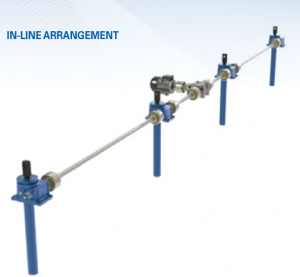
To give you an idea of how an in-line arrangement works in a company’s favor, here’s a real-life scenario to observe: A steel tube manufacturer is developing a new OD polisher that will increase production by 22 percent. Because of the increased production time, the set-up crew is unable to set the feed table manually and is looking to automate the feed table height using screw jack actuators.

The feed table length is 24 feet and weighs 5,600 pounds with the largest diameter steel pipe. The table height will need to change approximately once every 15 minutes, but no more than 10 times a day. Maximum height change is nine inches. The rate is .4 inches per second.

By our specifications, the in-line arrangement comes with a single three-HP AC Motor with 1750 RPM and drive, and it comes with the possibility to be removed and driven by hand. With hand-driven possibilities, a machine screw jack with a 24-to-1 gear ratio is needed to prevent back driving.

The mounting constraints call for an upright translating jack with a clevis rod end. Due to the length of the feed table, four jacks will be used in line with a center mounted motor through a single gearbox.

Other specifications for the in-line arrangement include a compression load, a total travel of 14 inches and the ability to move .25 inches in one second.

Get to Know Miniature Profile Ball Rail Lubrication Systems

mini profile ball rail

When dealing with miniature ball rail systems, having an effective lubrication system is essential for keeping the systems clean and running smooth. Miniature profile ball rail lubrication reduces friction and wear, prevents corrosion, dissipates heat and increases overall service life.

There are plenty of benefits to using industry-leading lubrication systems for miniature ball rails. Low-friction end seals effectively restrict dust while stainless steel endcaps act as scrapers, allowing for easy maintenance. Ball recirculation design, with hole and channel constructs fully sealed by a plastic frame and endcaps, reduces contact surface between steel ball and metal. This minimizes noise and adds to lubrication efficiency, reducing preventative maintenance.

A thin layer of oil separates the rolling elements from the raceway at the contact zone of the stainless steel ball rail. Lubrication systems allow the ball rails to move smoothly during short stroke movement. This lubrication assists in ensuring high-speed running production.

We recommend using LBL1, a lubricant formulated for rolling friction, with linear bearings. This lubrication is made to protect highly polished bearings from surface wear and corrosion.

Certain factors affect the reapplication levels, including speed, load, stroke length and operating environment. Practical observation is the only sure way to find a safe lubrication interval.

We recommend synthetic-oil based lithium with a viscosity between ISO VG32-100 soap grease if lubricant grease is required.

Ball Screw Solutions for Long Travel & High Speed

Design World’s always excellent Danielle Collins posted a great article about how Design Engineers can achieve both high speed and long travel with Ball Screws.

Didn’t know you could do that, did you?

Traditional solutions involve Belt Drives, Rack and Pinion Systems or Linear Motors. But each of those come with their own set of drawbacks. Ball Screws are an ideal solution for applications that are sensitive to thrust force or positioning accuracy

Yet Ball Screws are rarely looked at for high speed/long travel applications. Why?

Critical Speed

Any long cylindrical object will naturally sag in the middle. Add rotation, and you will get a whip effect, similar to a jump rope. The speed of rotation where that effect starts is the Critical Speed.

Obviously, one way to limit this effect would be to have a shorter unsupported span. But how do you limit the effect if your application calls for a long travel span?

The Solution – Ball Screw Supports

ball screw supports
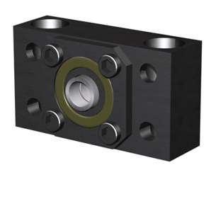
Some customers have made their own ball screw supports, usually paired on either side of the ball nut in pairs of 2, 4 or 6, to reduce the unsupported distance, essentially quadrupling the critical speed for each pair used. Depending on the application, they can even allow you to select a smaller diameter ball screw, without compromising performance.

So, have you used this solution? Or do you have an application where it might be a suitable alternative?