Ball Splines are convenient and efficient devices that allow friction-free linear motion while transmitting torque. Because of their reliability and high efficiency, they are utilized to replace conventional splines. In a ball spline assembly, recirculating bearing balls carry the load between the rotating member (inner race) and the rotating/translating member (outer race). These defined terms, processes and applications will give you a better idea of how and why ball splines matter in the precision engineering industry.
10 BALL SPLINE TERMS:
1. ACTIVE CIRCUITS
The closed path that the bearing balls follow through the outer race is referred to as a circuit. The number of potential circuits varies with the diameter of the spline shaft. When a circuit is loaded with bearing balls, it is referred to as an “active circuit.”
2. RETURN GUIDES
The outer race component through which the bearing balls are recirculated is referred to as the return guide.
3. BALL CIRCLE DIAMETER
The ball circle diameter is the diameter of the circle generated by the center of the bearing balls when in contact with the inner and outer race.
4. LAND DIAMETER
The land diameter is the outside diameter of the inner race. This diameter is less than the ball circle diameter.
5. ROOT DIAMETER
The root diameter is the diameter of the inner race measured at the bottom of the groove. This is the diameter used for critical speed calculations.
6. STRAIGHTNESS
Internal stresses may cause the material to bend. When ordering random lengths or cut material without end machining, straightening is recommended. Handling or machining of splines can also cause the material to bend. Before, during and after machining, additional straightening may be required.
7. LIFE
A ball spline assembly uses rolling elements to carry a load similar to an anti-friction (ball) bearing. These elements do not wear when properly lubricated during normal use. Therefore, ball spline life is predictable and is determined by calculating the fatigue failure of the components.
8. FRICTION
The use of rolling elements in a ball spline results in a low coefficient of friction.
9. ROTATIONAL LASH
Backlash or lash is the relative rotational movement of an outer race with no rotation of the inner race (or vice versa).
10. SELECTIVE FIT
When less than standard lash is required and a pre-loaded outer race cannot be used, outer races can be custom fit to a specific inner race with bearing balls selected to minimize rotational (angular) lash.
FIVE LOAD DEFINITIONS:
1. DYNAMIC TORQUE LOAD
The dynamic torque load is the torque load which, when applied to the ball spline assembly, will allow a minimum life of 1,000,000 inches of travel.
2. STATIC TORQUE LOAD
This is the maximum torque load (including shock) that can be applied to the spline assembly without damaging the assembly.
3. OVERTURNING LOAD
A load that rotates the outer race around the longitudinal axis of the inner race is an overturning load.
4. SIDE LOAD
This is a load that is applied radially to the outer race. Although a side load will not prevent the ball spline from operating, the outer race is not designed to operate with a side load, such as those generated from pulleys, drive belts or misalignment.
5. PRELOAD
Preload is a load introduced between an outer race and screw assembly that eliminates radial movement. Preloaded assemblies provide zero backlash for excellent repeatability and increased system stiffness.
OPTIONAL STANDARD KEYWAYS
Typically, outer races are mounted by machining a keyway into the outer race, inserting a key, and then sliding the outer race into a keyed bore. Standard machined keyways are available.
TRANSFERRING OUTER RACES FROM SHIPPING ARBOR:
STANDARD RACES
Ball spline outer races are shipped on arbors. Transferring the outer race from the arbor to the ball spline can be achieved by placing the arbor against the end of the spline and carefully sliding the outer race onto the inner race.
If the I.D. of the arbor is not able to slip over the O.D. of the end journal, apply tape to the journal to bring the O.D. up to the root diameter. The outer race can then be transferred across the taped journal onto the ball spline. Removal of the arbor from the outer race will result in the loss of the bearing balls. The set screw is used for transportation only and needs to be completely removed after installation.
LUBRICATION
Proper and frequent lubrication must be provided to achieve predicted service life. A 90% reduction in the ball spline life should be anticipated when operating without lubricants.
Standard lubrication practices for antifriction bearings should be followed when lubricating ball splines. A light oil or grease (lithium-based) is suitable for most applications. Lubricants containing solid additives such as molydisulfide or graphite should not be used.
Lubrication intervals are determined by the application. It is required that spline assemblies are lubricated often enough to maintain a film of lubricant on the inner race.
Ball screw lubricant protects against inter-ball friction, wear, corrosion and oxidation. We recommend E-900, a lubricant that will provide a lasting film for wear protection and resistance to corrosion. With an operating range of -65° to +375°F, E-900 has low rolling friction characteristics and helps reduce inter-ball friction in ball spline assemblies. For optimum results, the ball spline assembly should be in good repair and free of dirt and grease. Used regularly, lubrication will extend the life of ball spline assemblies. It should be applied generously on the entire length of the spline.
TEMPERATURE:
We use ball splines which will operate between -65°F and 300°F with proper lubrication.
END MACHINING:
Annealed ends can be provided on precision ball splines to facilitate end machining of journals.
END FIXITY:
End fixity refers to the method by which the ends of the spline are supported.
CRITICAL SPEED:
The speed that excites the natural frequency of the spline inner race is referred to as the critical speed. Resonance at the natural frequency of the inner race will occur regardless of orientation (vertical, horizontal, etc.).
The critical speed will vary with the diameter, unsupported length, end fixity and rpm. Since critical speed can also be affected by shaft straightness and assembly alignment, it is recommended that the maximum speed be limited to 80% of the calculated valve.


 For example, a leading cookie manufacturer could be adding a new product that requires a greater distance to the top heating element of the conveyor oven. The oven originally only had a static-top heating element and with this new order, it needs to be adjustable up to 14 inches. The top heating element weighs 5,000 pounds. The manufacturer anticipates only making adjustments to the height once or twice a month.
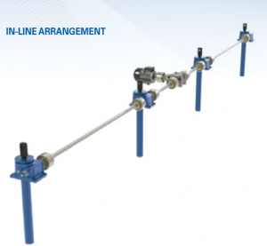
 To give you an idea of how an in-line arrangement works in a company’s favor, here’s a real-life scenario to observe: A steel tube manufacturer is developing a new OD polisher that will increase production by 22 percent. Because of the increased production time, the set-up crew is unable to set the feed table manually and is looking to automate the feed table height using screw jack actuators.