Getting the Best out of Your Linear Round Rail Bearings (Part 1)

In order to get the most life and best applications out of your bearings, it’s important to understand the size of the load, how the load will be applied and the length of the stroke. Applying too much weight to a load can significantly reduce the life and efficiency of your bearings. Also, incorrectly distributing the weight on the load can be harmful. In addition to some helpful design considerations, let’s take a look at the load considerations below.

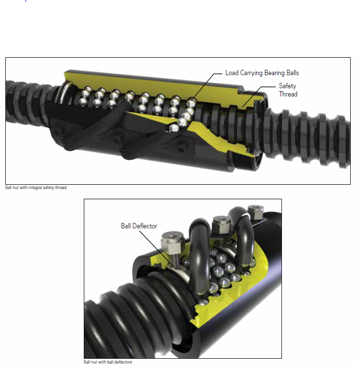
Load ratings are the required design life, shaft hardness and bearing dynamic that affect the load and can be applied to a linear bearing. Two dynamic load ratings are given for each bearing size based on the rotational orientation of the bearing.

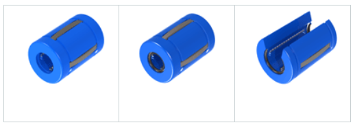
The normal load rating is used in applications where the orientation of the ball tracks relative to the load cannot be controlled. The normal load rating is based on a load imposed directly over a single ball track. The normal load rating shown in the specification tables is slightly greater than would be mathematically calculated based on one track loading, because it assumes that the load is shared to some degree by one or more of the adjacent ball tracks.

The maximum load rating assumes that the load is applied midway between two ball tracks as illustrated below. In this orientation the load is distributed over the maximum number of bearing balls.

The normal and maximum load ratings are based on a Rc 60 shaft hardness and a travel life of two million inches. For linear bearing system operating at less than full rated load, the Load-Life Curve may be used to determine the travel life expectancy.

An equivalent load value can be calculated when sizing linear bearings for applications at conditions other than maximum rating.

linear bearings

Design Considerations for Ball Screw Safety

There are several factors conducive to a ball nut failing prematurely, such as misalignment, impact loading, a lack of lubrication, contamination or external damage to the return circuits. However, the primary failure mode for ball nuts is fatigue of the bearing balls or thread surface. Premature failure may result in the loss of some or all of the balls between the nut and screw. When all the balls are lost, the nut is no longer engaged with the screw and therefore may not move when the screw is rotated or, in vertical applications, will free fall along the screw.

In applications where this loss of ball type failure could result in injury or death, this failure needs to be considered in the design. Possible preventative measures include the use of two or more screws supporting the load, use of nuts with multiple independent ball recirculation circuits, use of ball deflectors which prevent the balls from exiting the ball nut out the ends  or use of industry-leading integral safety thread ball nuts.

The integral safety thread is a unique solution that provides the ball nut with a secondary safety thread– a reverse thread in the nut body itself. This special thread extends from the ID of the nut to below the OD of the screw without making contact. In the unlikely event that all the balls in the nut are lost, this safety thread will engage the screw and prevent free fall.

Although this thread can be used to lower the load to a safe position, it is not to be used otherwise. This can also be accomplished with the use of a special flange if the ball nut body cannot accommodate the safety thread feature.

Ball safety

Three Popular Screw Types Defined

When considering the vast majority of applications in which machine screws are used, it’s important to review the functions of some of the major types of screws. Below, we’ll take a look at the designs, functions and more while we define acme, ball and planetary screws.

Acme Screws:

Acme

The acme screw thread, sometimes referred to as the trapezoidal thread, is used for lead screws. They are often needed for large loads, or when the environment is less than desirable.

The acme thread form has been around for over a century, replacing square thread screws which had straight-sided flanks and were difficult to manufacture.

There are two main classes of acme thread forms: general purpose (G) and centralizing (C). The general purpose and centralizing thread forms have a nominal depth of thread of 0.50 x pitch and have a 29 degree included thread angle, which has allowed companies to develop unique screw diameters and leads. European metric Trapezoidal thread forms have a 30 degree Included thread angle.

When compared to general-purpose thread forms, centralizing threads are manufactured with tighter tolerances and reduced clearance on the major diameter. For instance; If an acme nut is side loaded with a radial load, a “G” class will wedge when the nut thread flanks come in contact with the screw thread flanks. To prevent this wedging, a “C” class thread form can be used, since it utilizes less clearance and tighter tolerances are allowed between the major diameter of the nut and the major diameter of the screw.

Industry leaders have developed several unique thread forms, such as stub acme forms and 40 degree included angle, which allow them to provide a variety of diameter and lead combinations.

Ball Screws:

ball

For loads requiring a greater amount of efficiency, companies often turn to ball screws. A ball screw assembly is a device comprised of a nut, screw, and reciprocating ball bearings. The bearings provide the thread engagement between the nut and screw.

Ball screws offer an efficient means for converting rotary motion to linear motion. A ball screw is an improvement over an acme screw just as an anti-friction ball bearing is an improvement over a plain bushing.

In the long run, ball screw systems can prove to be a cost-effective alternative to pneumatic or hydraulic systems, which require constant electrical and air power.

Planetary Roller Screws:

Planetary

Planetary roller screws are remarkable devices designed to convert rotary motion into axial force or vice versa.

The planetary roller screw design offers multiple advantages and reliability for the most demanding applications when compared with other lead screw types due to its rolling motion. These screws offer high efficiency even in relatively shallow lead designs.

The multitude of contact points can carry large loads and provide very high resolution (small axial movement) when using very shallow leads. Planetary roller screws produce high rotational speeds with faster acceleration without adverse effects.

Benefits of Anti-Backlash Jacks

When working with ball screw systems, lashing can sometimes compromise the accuracy of the screw. Lash is the result of the axial movement between a nut and screw without rotation. While lash is not always a bad thing in an application, it can be controlled through preloading or the use of anti-backlash jacks.

Anti-backlash machine screw jacks may be used wherever reversible load conditions require precision positioning control. Leading adjustable backlash machine screw jack models are available to reduce backlash to approximately 0.003 inches.

There are number of advantages for using anti-backlash jacks in your applications. An anti-backlash machine screw jack allows the lash between the drive sleeve thread and the lifting screw thread to be controlled by adjusting the top cover of the jack. The anti-backlash jack design has an upper drive sleeve and a lower drive sleeve.

Adjustment of the cover changes the relative distance between the drive sleeves. This change in distance compensates for any lash. Because the drive sleeve is split, the life of an anti-backlash machine screw jack will be less.

Anti-backlash machine screw jacks minimize backlash, but should not be used to completely eliminate backlash. While it may be desirable to totally eliminate backlash, the result would be a lock-up of lifting shaft and drive sleeve.
abl jack

Key Considerations for Choosing Worm Gear Screw Jacks

MachineScrewJackWorm gear screw jacks can be found in a great number of industries, including military, automotive, manufacturing and many more. When choosing the right kind of worm gear screw jack for your product, here are just a few crucial industry considerations and specifications to keep in mind.

→ Worm gear screw jacks built up to leading industry standards are rated for up to 3,000 rpm input speed, provided horsepower and temperature ratings are not exceeding.

→ Top worm gear jack models are ruggedly designed and produced in standard styles with load-handling capabilities from 1/4- to 100-ton and can be used individually or in multiple arrangements.

→ For duty cycles, the cycle is limited by the ability of the worm gear screw jack to dissipate heat. An increase in temperature can affect the properties of some components resulting in accelerated wear damage and possible unexpected failure. The approximate allowable duty cycles are 35 percent for ball screw jacks and 25 percent for machine screw jacks. The rolling action of these screw jacks reduces friction for smooth and efficient load movement, providing higher speed operation and increased duty cycle.

→ Leading worm gear screw jacks are made to be suitable for temperatures no lower than 20 degree below Fahrenheit and no higher than 200 degrees Fahrenheit. Continuous or heavy duty operation is possible by operating the jack capacity, external cooling of the unit or through the use of a recirculating lubrication system.

→ Leading machine screw jacks incorporate an Acme screw with a 2C thread form. With a 20:1 or greater gear ratio, the jacks are considered self-locking. A drive sleeve including the Acme thread form makes an anti-backlash option possible.

A Nook Industries Publication